


Basic Datacenter Switching
In this article, I am going to talk about the traffic flow or you can say the representing the logical topology using virtualized VDC. Before we will start with the further discussion just have a look on the basic datacenter environment with all the four layers.
Logical topology example using services VDC sandwich
physical model
Lets talk about the topology and the traffic flow
- Layer-2 only services chassis with transparent service contexts
- VLANs above, below, and between service modules are a single IP subnet
- Sub-aggregation VDC is a layer-3 hop running HSRP providing default gateway to server farm subnets
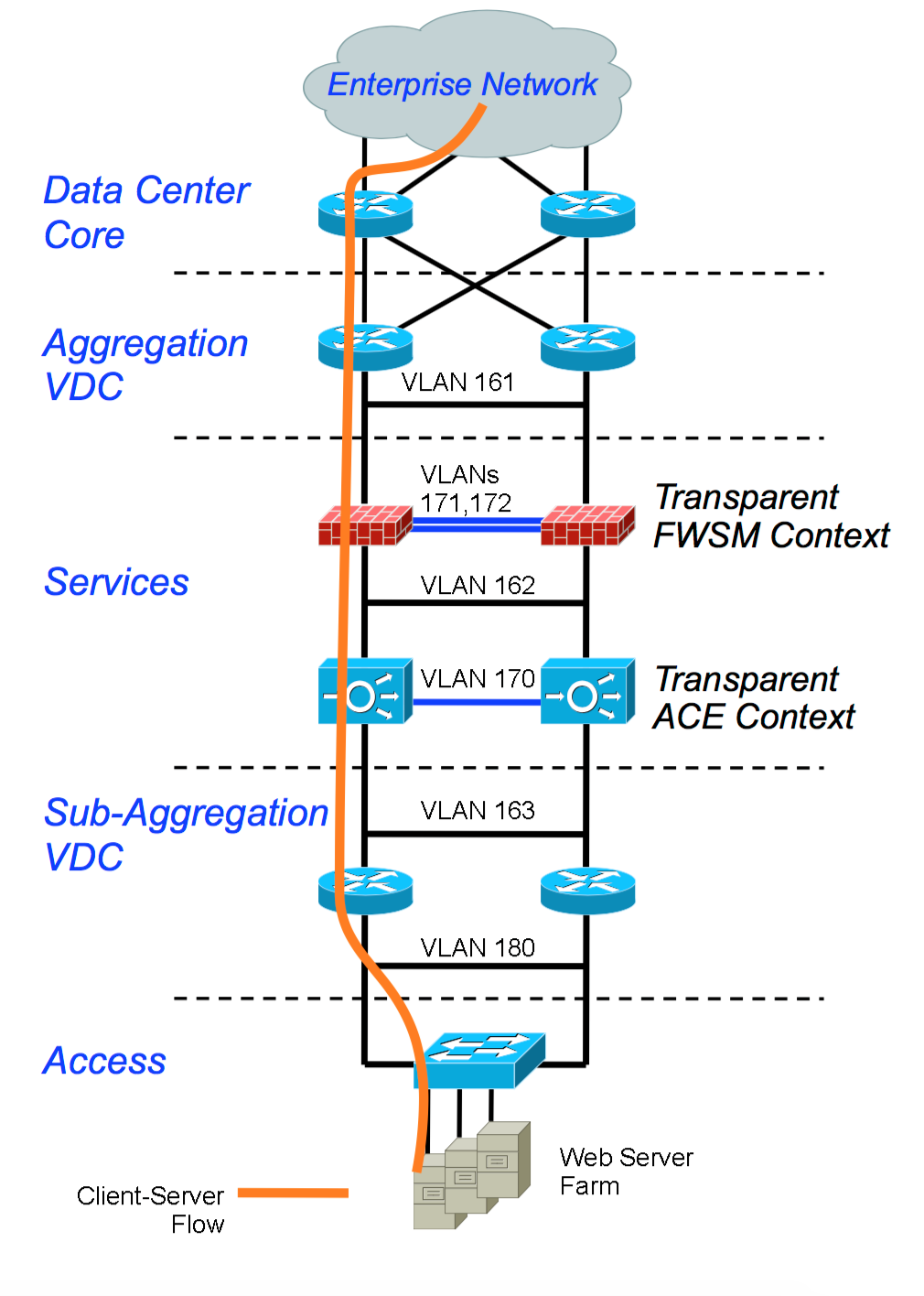 |
Fig 1.1- Logical Topology example using VDC model
|
- Multiple server farm VLANS can be served by a single set of VLANs through the services modules
- Traffic between server VLANs does not need to transit services device, but may be directed through services using virtualization
Logical Topology to support multi-tier application traffic flow
- Same physical VDC services chassis sandwich model
- Addition of multiple virtual contexts to the transparent services modules
- Addition of VRF routing instances within the sub-aggregation VDC
 |
Fig 1.2- Logical Topology example using VDC model multi-tier application Flow
|
- Service module contexts and VRFs are linked together by VLANs to form logical traffic paths Example Web/App server farm and Database server cluster homed to separate VRFs to direct traffic through the services


